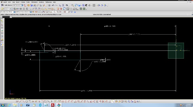
A sketch is made and all the lines and curves are defined and constrained.
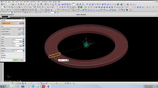
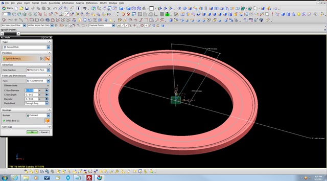
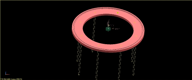
Once the drawing is reviewed, a solid 3D model is made for each step in the procedure. A model will be made to the specs of the actual raw material or forging that will enter the shop through the loading dock. As each operation does some type of machining step to it, a new model will be made to show the actual part as it goes through each step. This allows the Engineer or designer to test the fixturing or machine setup with the actual state of material that is being worked on. Sometimes the raw material will be quite differeent from the end results. We've had parts that willl have a few thousand pounds of material taken off in machining operations. When designing the fixtures, they also are modeled and the parts in various stages can be loaded into them in the virtual environment to check to see if everything is working ok.
We use Unigraphics NX for our modeling, but this is probably the costliest and best CAD/CAM software available. A lot of shops will use separate programs for CAD modeling, Drafting and CAM (Computer Aided Machining) like maybe Solid Works for modeling and Mastercam for CAM. The advantage to using NX is that besides being one of the higher end modeler, you can also have CAD, CAM, Drafting, Visualization, Assembly and even FEA applications all in one package. This eliminates the need to translate files between all the applications.
|
|
|
 |
These pics describe some of the basics. It would be impossible even scratch the surface of this in quite a few webpages. More can be seen by checking out the Unigraphics NX info online.