I've been learning to use the NX6 graphic modeling program at school. This is one of the neatest programs I've ever had the pleasure to work with. You can sketch items and then extrude them into solid parts. Then you can add features using additional sketches and datum planes or use form features such as bosses, blocks, cylinders and pads. You can also extrude pieces away from objects or subtract material with holes, pockets, grooves and slots. Features can also be mirrored and both circular and rectangular arrays for features can be made.
You can then take your freshly made parts and assemble them into an assembly, adding constraints to keep it together. You can then check clearances, rotate and flip assemblies and put forces on items. You can get weights and masses for different materials chosen. When all is done, you can create assembly drawings, CNC programs for machine work or molds for castings.
Here is a radial engine assembly I made and assembled:
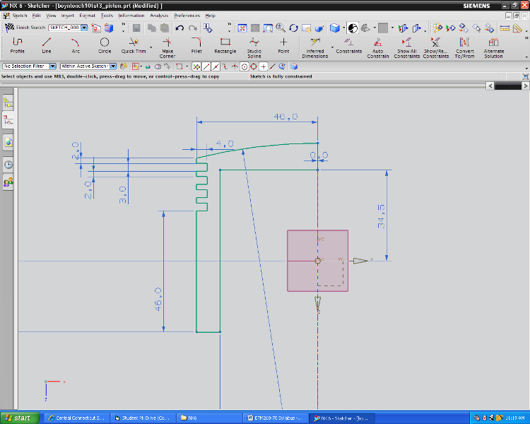
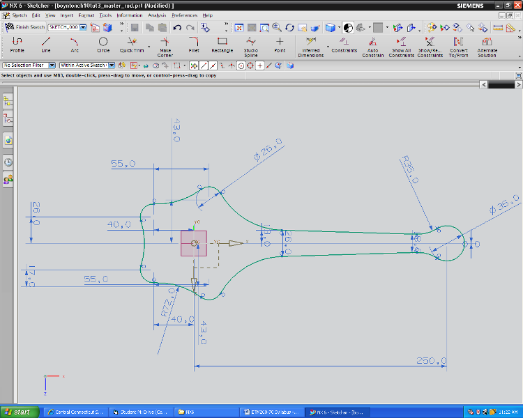
First I started with the piston, I will only have to make one of these and then load it five times for each of the five separate pistons in the engine. I sketch the profile from the center axis to one side and then reference all dimensions, set lines equal to each other and horizontal or parallel. I set radiuses and reference all of this to the center data coordinate system.
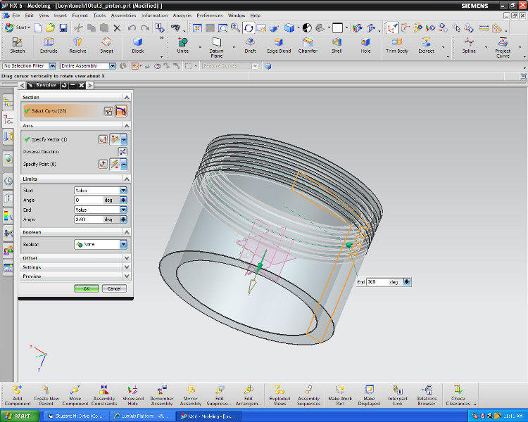
I then rotate this sketch around the center datum axis and rotate it a full 360 degrees to unite the beginning to the end. This makes the solid piston shown.
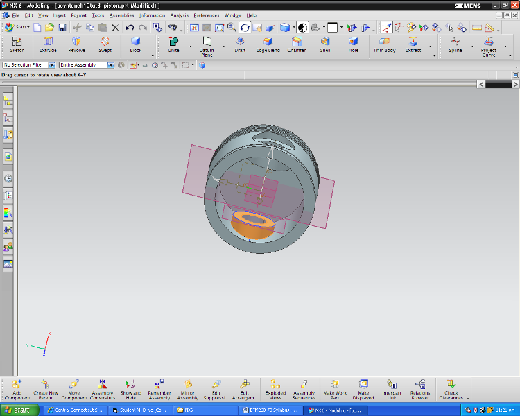
I then add a datum plane at a certain distance from the datum center plane and use that plane to sketch a circular feature to extrude and unite into the piston body to create the inside piston pin boss. This is shown above. Those features were then mirrored to the other inside surface of the piston. Finally a counterbore and hole were made for the piston pin
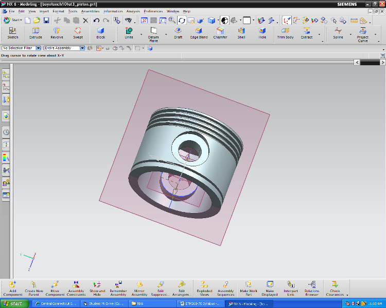
The completed piston
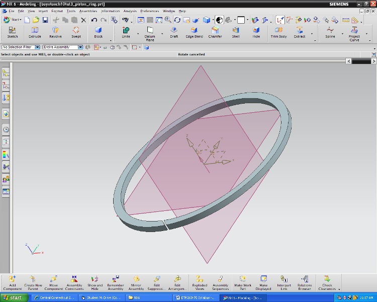
I then made a bunch of smaller parts and saved them into part files. I made the ring, shown here from a sketch and an extrusion. I added a datum plane to the part so it can be constrained in an assembly without rotating. This single ring file will be loaded into assemblies a total of twenty times.
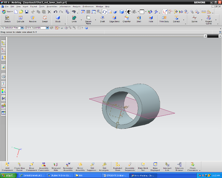
The piston bushing here (with a plane to define a non-rotating constraint in the assembly environment). A top bushing, a master rod bushing, piston pin,, and piston pin plugs were also made but not shown here.
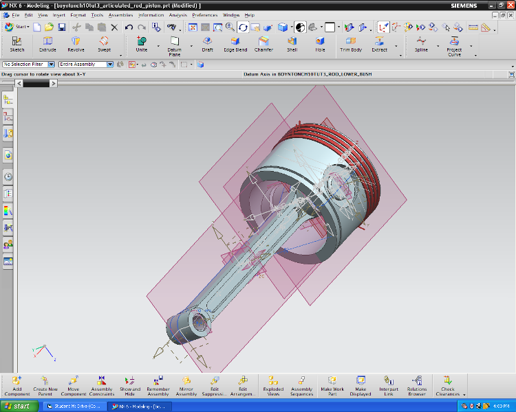
The piston, four instances of the rings, a piston pin, and plugs were all assembled into a sub-assembly and that file was constrained together and saved. The color of the rings were changed to make them contrast for a better view. You can see the lower rod bushing assembled at a recessed level in the bottom of the rod. The plane in the center of that bushing allowed me to constrain it against rotation.
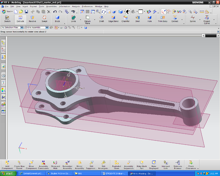
A master piston was made from a few sketches, some extrusions and a revolve. this was quite a tricky part to make because there were many non-linear surfaces. It came out pretty well, though.
This is the starting sketch for that master piston, it was pretty time consuming but it extruded nicely. Then a number of other sketches, adding holes, extruding added material in spots and subtracting material in others made the final piece.
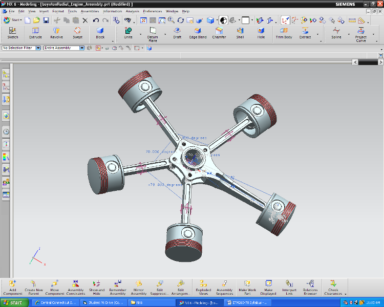
A piston, rings, pins and plugs were added to the master rod and four piston/rod subassemblies were added and linked to the rod. These parts were constrained using angles and aligning centerlines to make the final radial engine piston unit. Of course, I can rotate this assembly to any view or blow it up in size to check small details.